MIL-PRF-19E
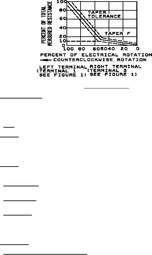
FIGURE 3. Counterclockwise Taper.
3.4.5 Contact-arm assembly. Contact pressure on the resistance element shall be maintained uniformly by
positive pressure and shall be such as to permit smooth electrical and mechanical control of the resistor over the
entire range of electrical rotation (see 3.1) within the resistance rating. The rotating contact shall have continuous
electrical contact with its terminal through the entire mechanical rotation and shall be electrically insulated from the
operating shaft, bushing, and resistor housing.
3.4.5.1 Stops. A stop shall be employed to limit the mechanical rotation of the contact arm assembly.
3.4.6 Terminals. Resistors and attached switches shall be supplied with external terminal lugs or terminal lugs of
such size and style as to permit accommodating and soldering of three 0.032 inch (0.81mm) diameter (AWG size 20,
stranded or equivalent) wires for resistors with 0.250 inch (6.35 mm) diameter operating shaft, and three 0.025 inch
(0.64 mm) diameter (AWG 22 solid or equivalent) wires for resistors with 0.125 inch (03.18 mm) diameter operating
shafts. Terminal shall be treated to facilitate soldering.
3.4.7 Hardware. Each resistor shall be furnished with a corrosion-resistant, internal tooth lockwasher, a hexagonal
mounting nut, and a locking nut of the size specified (see 3.1). Hardware shall not be assembled on the resistor
unless otherwise specified (see 6.2). For direct Government orders, hardware shall be assembled on the resistor.
3.4.7.1 Standard bushings. When standard bushings are specified, the bushing shall be as shown for the
applicable style of resistor (see 3.1).
3.4.7.2 Locking bushings. When locking bushings are specified, the bushing shall be as shown for the applicable
style of resistor (see 3.1).
3.4.7.3 Nonturn device. A nonturn device shall be furnished on resistors, which will prevent their rotation with
respect to surface on which they are mounted. The location of the nonturn device and its widest dimension shall be
as specified (see 3.1). If the nonturn device is not symmetrical about it's vertical axis, it shall be so placed that a
plane passed perpendicular to the widest dimension and through its center shall pass through the axis of the
operating shaft, and shall be an integral part of the resistor or permanently attached thereto.
3.4.8 Threaded parts. All threaded parts shall be in accordance with FED-STD-H28 and as specified (see 3.1).
3.4.8.1 Securing of screws, nuts, and threaded parts. All screw-thread assemblies shall be made resistant to
loosening under vibration.
6
For Parts Inquires call Parts Hangar, Inc (727) 493-0744
© Copyright 2015 Integrated Publishing, Inc.
A Service Disabled Veteran Owned Small Business