MIL-PRF-19E
O
105
O
40
100
80
60
40
20
0
-40
-30
-20
0
20
40
60
80
100
120
140
O
Ambient Temperature ( C)
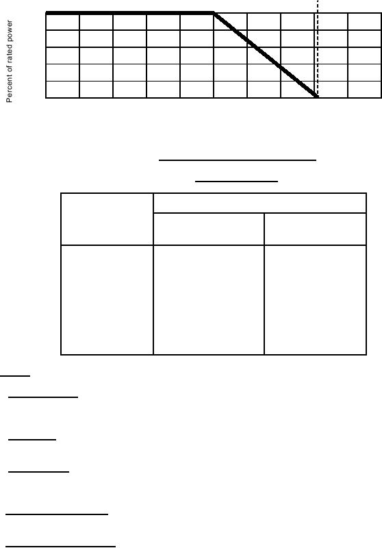
FIGURE 4. Power rating curve for continuous duty.
TABLE VI. Minimum resistance.
Maximum resistance at minimum setting
Total resistance
nominal
All styles with 0.25 inch
All styles with 0.125 inch
(in ohms)
diameter shaft
diameter shaft
(in ohms)
(in ohms)
Up to and including 15
5.0
Over 15
3.0
3 to 50 inclusive
0.3
51 to 100 inclusive
0.5
0.2 percent of the nominal
over 100
resistance value or 1.0 ohm
which ever is greater
3.9 Torque (see 4.7.4).
3.9.1 Operating torque. When resistors are tested as specified in 4.7.4.2, the torque required to rotate the contact
arm shall be as specified (see 3.1). An additional torque of 15 once-inches shall be permitted for operation of
attached switches.
3.9.2 Stop torque. When resistors are tested as specified in 4.7.4.3, resistors shall withstand the stop torque
specified (see 3.1) without damage to the contact arm, stop and nonturn device.
3.9.3 Locking torque. When resistors are tested as specified in 4.7.4.4, resistors with locking bushings shall
withstand the locking torque specified (see 3.1) without damage to the bushings, threads and nonturn device. The
resistance value shall not change in excess of 3 percent of the total resistance value.
3.10 Low temperature storage. When resistors are tested as specified in 4.7.5, the maximum change in resistance
shall not exceed ±4 percent.
3.11 Low temperature operation. When resistors are tested as specified in 4.7.6, the torque required to effect
rotation of the contact arm shall not be greater than 40 ounce-inches. This includes switch action if attached. The
maximum change in resistance shall not exceed ±4 percent.
8
For Parts Inquires call Parts Hangar, Inc (727) 493-0744
© Copyright 2015 Integrated Publishing, Inc.
A Service Disabled Veteran Owned Small Business