MIL-PRF-914C
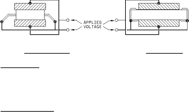
FIGURE 4. Test fixture for gullwings.
FIGURE 5. Test fixture for LCC.
MIL-STD-202. The following details shall apply:
a.
Test condition A.
Special preparation: As specified in 4.8.13.1a.
b.
c.
Points of measurement: As specified in 4.8.13.1e.
4.8.15 Resistance to soldering heat (see 3.20). Networks shall be tested in accordance with method 210 of
MIL-STD-202. The following details and exceptions shall apply:
a.
Measurement before test: DC resistance shall be measured as specified in 4.8.5
b.
Mounting and testing: Networks shall be mounted on a fiberglass test board as specified in 4.8.1, method B
and test condition J except the temperature shall be 245 C ±5 C. This mounting procedure shall count as
O
O
one heat cycle.
c.
Second cycle: The heat cycle portion of step b above shall be repeated. (NOTE: When a hot plate is used,
the temperature shall be 245 C ±5 C for 60 ±5 seconds and the temperature ramp and emersion/immersion
O
O
rate does not apply).
d.
Measurement after the test: After completion of the cleaning process and following a 30 minute +90 minute,
-15 minute cooling period, the dc resistance shall be measured as specified in 4.8.5. The change in
resistance shall not exceed the value specified in table I.
e.
Examination after the test: Networks shall be examined for evidence of mechanical damage.
30
For Parts Inquires call Parts Hangar, Inc (727) 493-0744
© Copyright 2015 Integrated Publishing, Inc.
A Service Disabled Veteran Owned Small Business