MIL-PRF-914C
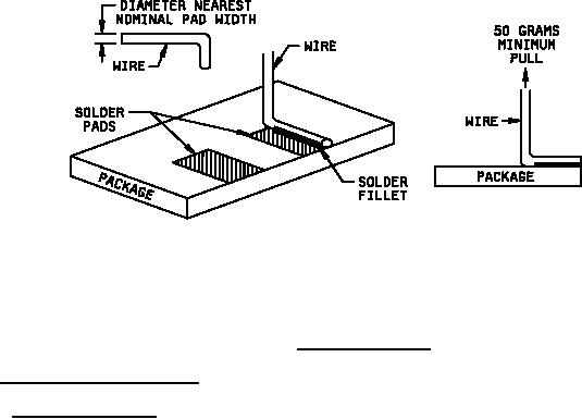
Material:
Flux: Type A or B, per J-STD-004
Solder: SN60A or SN63A, per J-STD-006
Wire: Soft Annealed Solid Copper
FIGURE 3. Adhesion test fixture.
4.8.13 Dielectric withstanding voltage (see 3.18).
4.8.13.1 Atmospheric pressure. Networks shall be tested in accordance with method 301 of MIL-STD-202. The
following details shall apply:
a.
Mounting: For gullwing packages, the network shall be clamped by mounting with its top on a metal plate of
sufficient size to extend beyond the network extremities. An additional metal plate shall be mounted against
the bottom of the network, avoiding contact with the terminals. The terminals of the network shall be
connected together (see figure 4). For LCC packages, the network shall be clamped by mounting its
top/bottom on a metal plate of sufficient size to cover the nonterminated body surface; care should be taken
not to short out the terminations on both the top and bottom. The terminals of the network shall be
contacted together (see figure 5).
b.
Magnitude of test voltage: 200 volts rms.
c.
Nature of potential: An ac supply at commercial-line frequency (not more than 100 hertz (Hz)) and
waveform.
d.
Duration of application of test voltage: 60 seconds +10 seconds, -0 seconds.
e.
Points of application of test voltage: Between the terminals connected together and the metal-mounting
plates.
f.
Inspections and measurements: During the tests, the leakage current shall be monitored and the networks
inspected for evidence of arcing and breakdown. At the conclusion of the test, networks shall be inspected
for evidence of damage.
29
For Parts Inquires call Parts Hangar, Inc (727) 493-0744
© Copyright 2015 Integrated Publishing, Inc.
A Service Disabled Veteran Owned Small Business