MIL-PRF-39015E
4.8.23 Rotational life (see 3.29).
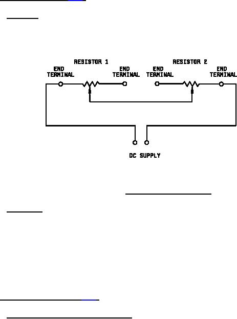
4.8.23.1 Mounting. Resistors shall be mounted in such a manner as to allow electrical connections to
be made to the terminals and concurrent contact arm actuation of each "pair" of resistors. The resistors
shall be ganged in pairs, and each pair shall be connected in series, as shown in figure 4, so that a
nominally constant current flows through the resistors, irrespective of the contact arm position during the
turning of the operating shaft.
FIGURE 4. Rotational life test circuit.
4.8.23.2 Procedure. Total resistance shall be measured as specified in 4.8.4.1. A dc potential,
equivalent to that required to dissipate rated wattage across the entire resistive element of resistors
having the same nominal total resistance as those under test, shall then be applied as shown in figure 4.
The lead screw actuators shall be continuously cycled through 90 percent to 100 percent of the actual
effective electrical travel, at the rated one cycle for 2.5 minutes, for a total of 200 cycles. A cycle shall
consist of travel through 90 percent to 100 percent of actual effective electrical travel and return to the
starting point. At no time during this test shall the contact arm be allowed to idle at either end of the
travel. After rotation, total resistance shall be measured as specified in 4.8.4.1. Resistors shall then be
examined for evidence of mechanical damage.
4.8.24 Terminal strength (see 3.30).
4.8.24.1 Pull (applicable to all terminal types). Resistors shall be tested in accordance with
method 211 of MIL-STD-202. The following detail and exception shall apply:
a. Test condition A: Applied force 2 pounds. Resistors clamped by the resistor body, force applied
to each lead individually.
b. Measurement after test: Resistors shall be examined for evidence of mechanical damage, and
tested for electrical continuity.
30
For Parts Inquires call Parts Hangar, Inc (727) 493-0744
© Copyright 2015 Integrated Publishing, Inc.
A Service Disabled Veteran Owned Small Business