MIL-PRF-55342/9E
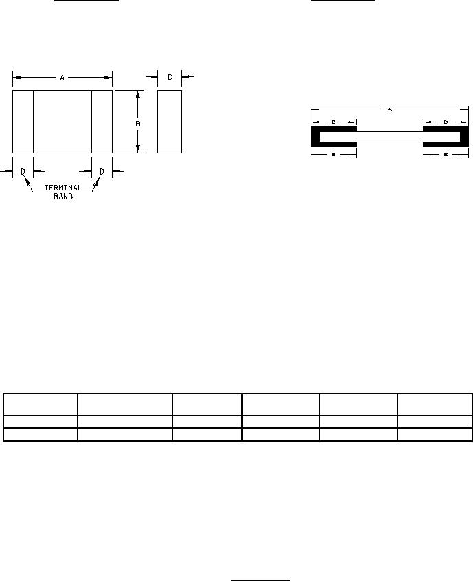
Configuration B
Configuration A
Inches
mm
Inches
mm
.005
0.13
.030
0.76
.009
0.23
.033
0.84
.012
0.30
.124
3.15
.015
0.38
.248
6.30
.020
0.51
.259
6.58
Configuration
Dimension A
Dimension B
Dimension C
Dimension D
Dimension E
inch
inch
inch
Inch
inch
.248 ±.005
.124 ±.005
.015 ±.005
A
.012/.030
N/A
.124 ±.005
.020 ±.005
.020 ±.005
B
.259 +0.009, -0.015
.015/.033
NOTES:
1. Dimensions are in inches.
2. Metric equivalents are given for general information only.
3. Unless otherwise specified, tolerance is ±.005 (0.13 mm).
4. The pictorial view of the styles above are given as representative of the envelope of the item. Slight deviations
from the outline shown, which are contained within the envelope, and do not alter the functional aspects of the
device are acceptable.
5. Configuration A covers termination materials D, T, and W.
6. Configuration B covers termination materials B, C, G, and U.
*
FIGURE 1. Style RM2512.
3
For Parts Inquires call Parts Hangar, Inc (727) 493-0744
© Copyright 2015 Integrated Publishing, Inc.
A Service Disabled Veteran Owned Small Business