MIL-PRF-39002C
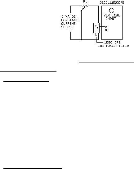
FIGURE 3. Peak noise measuring circuit.
4.6.7 Dielectric withstanding voltage (see 3.12).
4.6.7.1 At atmospheric pressure. Resistors shall be tested in accordance with method 301 of MIL-STD-202. The
following details shall apply:
a.
Special preparation: Resistors shall be mounted on metal plates of sufficient size to extend beyond the
resistor extremities, and in such a manner that measurements can be made between the terminals tied
together and any other external metal parts.
b.
Magnitude of test voltage: 900 V rms.
c.
Nature of potential: From an alternating current (ac) supply at commercial-line frequency and waveform.
d.
Points of application of test voltage: Between the terminals connected together and all external metal
portions of the resistors and metal-mounting plate.
e.
Examinations and measurements: During the tests, the leakage current shall be monitored and the resistors
examined for evidence of arcing and breakdown. At the conclusion of the test, resistors shall be examined
for evidence of damage.
4.6.7.2 At reduced barometric pressure. Resistors shall be tested in accordance with method 105 of
MIL-STD-202. The following details and exceptions shall apply:
Method of mounting: As specified in 4.6.7.1a.
a.
b.
Test condition letter: D.
c.
Period of time at reduced pressure prior to application of potential: 1 minute.
d.
Tests during subjection to reduced pressure: A potential of 250 volts rms from an ac supply at commercial-
line frequency and waveform shall be applied for 1 minute.
e.
Points of application: As specified in 4.6.7.1d.
f.
Examinations and measurements: As specified in 4.6.7.1e.
14
For Parts Inquires call Parts Hangar, Inc (727) 493-0744
© Copyright 2015 Integrated Publishing, Inc.
A Service Disabled Veteran Owned Small Business