MIL-PRF-26H
4.7.10.2 Procedure. DC resistance shall be measured as specified in 4.7.2 at room ambient temperature.
Resistors shall be exposed to an ambient temperature of 250 C ± 7 C (for characteristic U) and 350 C ± 7 C (for
O
O
O
O
characteristic N and characteristic V) for a period of 250 hours ± 8 hours. Not less than 2 hours after the end of the
exposure period, the dc resistance shall again be measured as specified in 4.7.2 at room ambient temperature. For
axial-terminal resistors, the wire leads may be cleaned before the resistance measurement.
4.7.11 Moisture resistance (see 3.15). Resistors shall be tested in accordance with method 106 of MIL-STD-202.
The following details and exceptions shall apply:
a.
Mounting: For resistors under load a space of 1 inch minimum shall be maintained for axial-terminal
resistors and 2-1/2 inches minimum for all other resistors between test parts and as follows:
(1) Tab-terminal, flat (stack-mounting) resistors: By means of mounting bolts or screws as in normal
service.
(2) Tab-terminal, tubular resistors: Four (two high and two low) of the specimens, by means of their
associated mounting hardware and supplementary insulation; the remaining six (three high and three
low), as specified in 4.7.8.1a.(2).
(3) Axial-terminal resistors: Soldered by their leads to rigid mounts or terminal lugs. The spacing of the
mounts or terminal lugs shall be such that the length of each resistor lead is approximately .375 inch
(9.53 mm) when measured from the edge of the supporting terminal to the resistor body. Six (three
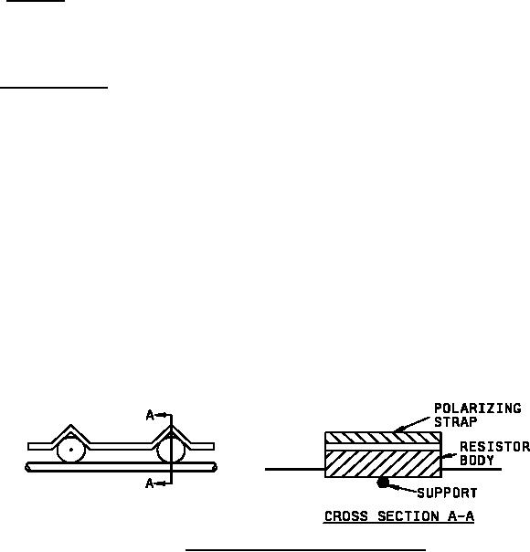
high and three low) of the sample units shall be covered with a V-shaped metal strap whose width is
equal to the length of the resistor body as indicated on figure 2. The strap shall be made of a corrosion-
resistant metal and shall be kept in contact with the resistor body by supporting the body as indicated
on figure 2, with a nonconducting, noncorrosive, support whose width is less than that of the body and
which shall not act as a moisture trap. The mounting straps may be individual for each resistor or
continuous for all resistors. These resistors with strapping shall be subjected to the polarization voltage.
FIGURE 2. Mounting straps for moisture-resistance test.
b.
Initial measurement: Immediately following the initial drying period, dc resistance shall be measured as
c.
Polarization and loading voltage: Three units of highest resistance value and three units of lowest
resistance value shall be subjected to polarization and two units of highest resistance value and two units of
lowest resistance value shall be subjected to loading voltage as follows:
(1) Polarization: During steps 1 to 6 inclusive, a 100 volt dc potential shall be applied with the positive lead
connected to the resistor terminals tied together, and the negative lead connected to the mounting
hardware or polarizing straps as applicable. This procedure is applicable to 6 of the sample units
mounted as follows:
16
For Parts Inquires call Parts Hangar, Inc (727) 493-0744
© Copyright 2015 Integrated Publishing, Inc.
A Service Disabled Veteran Owned Small Business