MIL-PRF-22097J
APPENDIX A
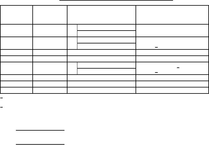
TABLE A-I. Additional testing required to extend qualification to other styles.
Terminal type
Number of additional
Tests from table V to be performed
Terminal types
for which
sample units
on additional sample units
qualified
qualification is
sought
3 highest resistance value
Test group I moisture resistance and
P, S, W, or X
L
6
terminal strength
3 lowest resistance value
3 highest resistance value
Test group I and III and terminal
P
S, W, or X
6
strength 1/
3 lowest resistance value
P
Y
6 any resistance value
Visual and mechanical inspection
S, L, or X
P
6 any resistance value
Visual and mechanical inspection
6 highest resistance value
Test groups I, III, VII 2/ and terminal
L
P, W, or X
9
strength 1/
3 lowest resistance value
W or X
P
6 any resistance value
Visual and mechanical inspection
X
W
6 any resistance value
Visual and mechanical inspection
W
X
6 any resistance value
Visual and mechanical inspection
1/
Where terminal strength is required the six sample units from the previous test, or six additional sample units
may be used at the option of the supplier.
2/
All nine sample units shall be submitted to test group I, then subdivided with six sample units submitted test
group III and the remaining three sample units submitted to test group VII.
A.5. SOLDER DIP (RETINNING) LEADS
A.5.1 Solder dip (retinning) leads. The manufacturer may solder dip/retin the leads of product supplied to this
specification provided the solder dip process has been approved by the qualifying activity.
A.5.2 Qualifying activity approval. Approval of the solder dip process will be based on one of the following options:
a.
When the original lead finish qualified was hot solder dip lead finish 52 of MIL-STD-1276. (NOTE: The 200
microinch maximum thickness is not applicable). The manufacturer shall use the same solder dip process
for retinning as is used in the original manufacture of the product.
b.
When the lead originally qualified was not hot solder dip finish 52 of MIL-STD-1276 as prescribed in A.5.2a,
approval for the process to be used for solder dip shall be based on the following test procedure:
(1) Thirty samples of any resistance value for each style and lead finish are subjected to the manufacturer's
solder dip process. Following the solder dip process, the resistors are subjected to the dc resistance
test (and other group A electricals). No defects are allowed.
(2) Ten of the 30 samples are then subjected to the solderability test. No defects are allowed.
(3) The remaining 20 samples are subjected to the resistance to soldering heat test followed by the
moisture resistance test. No defects are allowed.
29
For Parts Inquires call Parts Hangar, Inc (727) 493-0744
© Copyright 2015 Integrated Publishing, Inc.
A Service Disabled Veteran Owned Small Business