MIL-PRF-22097J
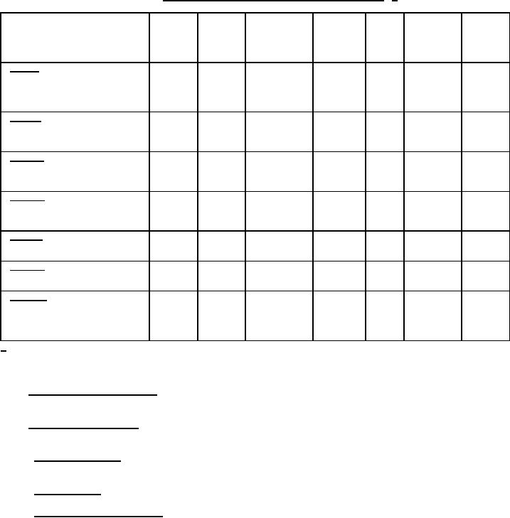
TABLE XII. Sequence for inspections, measurements, and tests. 1/
Dielectric
Resistance
Contact
withstanding
measured
Total
Insulation
Setting
Inspection
voltage (at
resistance
Torque
between
resistance
resistance
stability
atmospheric
variation
terminals
pressure)
1 and 3
Group I
Visual and mechanical inspection
A
Atmospheric
Actual effective electrical travel
and barometric
End resistance
Thermal shock
B, A
A
A
A
B, A
Group II
Resistance temperature
characteristic
Moisture resistance
B, A
A
A
Group III
Shock (specified pulse)
B, A
B, A
Vibration, high frequency
B, A
A
A
B, A
Salt spray (corrosion)
Group IV
Resistance to soldering heat
B, A
(terminal types P, S, W, X, Y)
Life
B, A
A
A
A
B, D, A
B, A
Group V
Low temperature operation
B, A
A
B, A
High temperature exposure
B, A
A
A
A
A
B, A
Group VI
Rotational life
B, A
A
Terminal strength
Group VII
Solderability
(terminal types P, W, X, Y)
Immersion
(terminal types P, W, X, Y)
1/ B: Before test.
D: During test.
A: After test.
6.8 Supersession of characteristic. Characteristic B has been deleted. Resistors having characteristic B is
replaced by resistors having characteristic C.
6.9 Reduction of power rating. When only a portion of the resistance element is engaged, the wattage rating is
reduced in approximately the same proportion as the resistance.
6.10 Stacking of resistors. When stacking of resistors, care should be taken to compensate for the added rise in
temperature by derating the wattage rating accordingly.
6.11 Retinning leads. If retinning (hot solder dip) of the leads is required see appendix A.
6.12 Subject term (key word) listing.
Ohmic
Potentiometer
Resistance
Trimmer
Multiturn
Single turn
26
For Parts Inquires call Parts Hangar, Inc (727) 493-0744
© Copyright 2015 Integrated Publishing, Inc.
A Service Disabled Veteran Owned Small Business