MIL-PRF-22097J
d.
Test procedures: Moisture resistance cycling requirements shall be 20 cycles.
e.
Final measurements: Upon completion of step 6 of the final cycle, the resistors shall be removed from the
chamber and air dried for one-half hour at room ambient conditions. Samples shall not be subjected to force
air drying. The total resistance and insulation resistance shall then be measured 30 minutes to 45 minutes
after removal from the humidity chambers, as specified in 4.7.2.1 and 4.7.6, respectively. The subsequent
24 hour conditioning period and measurements do not apply.
f.
Inspection after test: Resistors shall be inspected for evidence of mechanical damage.
g.
Steps 7A and 7B; Steps 7A and 7B are not applicable to this specification.
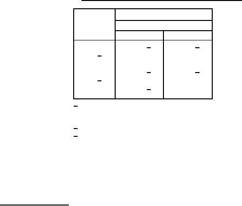
TABLE XI. Resistance temperature characteristic test temperature.
Temperature (OC)
Sequence
Characteristic
A
C and F
1
25 1/
25 1/
2 2/
-25
-15
3
-55
-55
4
25 1/
25 1/
5 2/
55
65
6
85 3/
7
125
150
1/ This temperature shall be considered the
reference temperature for each of the
succeeding temperatures.
2/ Not applicable in conformance inspection.
3/ This temperature applicable to
characteristic A only.
NOTE:
At the option of the manufacturer, the reverse sequence may be as follows:
1.
Room temperature.
+150 C �3 C.
O
O
2.
3.
Room temperature.
-55OC �3OC.
4.
4.7.11 Shock (specified pulse). Resistors shall be tested in accordance with method 213 of MIL-STD-202
(see 3.16). The following details and exceptions shall apply:
a.
Special mounting means: Resistors shall be mounted by their normal mounting means and within their
bodies restrained from movement on an appropriate mounting fixture. The mounting fixture shall be
constructed in such a manner as to insure that the mounting supports remain in a static condition with
reference to the shock test table. Resistors shall be mounted in relation to the test equipment in such a
manner that the stress applied is in the direction which would be considered most detrimental.
b.
Test leads: Test leads used during this test shall be no larger than AWG size 22 stranded wire, so that the
influence of the test lead on the resistor shall be held to a minimum. The test lead length shall be no longer
than necessary.
Measurement before shock: Total resistance and setting stability shall be measured as specified in 4.7.2.1
c.
and 4.7.8.1, respectively.
d.
Test condition I.
20
For Parts Inquires call Parts Hangar, Inc (727) 493-0744
© Copyright 2015 Integrated Publishing, Inc.
A Service Disabled Veteran Owned Small Business