MIL-PRF-22097J
4.7.3 Actual effective electrical travel. The actual effective electrical travel shall be measured by placing the
resistor in a device and circuit which will indicate both angular position of the operating shaft and voltage output. The
actual effective electrical travel will be the number of turns or degrees of the operating shaft in which a change in
contact arm position gives a measurable change in voltage output (see 3.8).
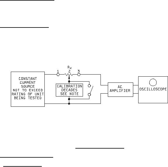
4.7.4 Contact resistance variation. Contact resistance variation shall be measured with the measuring circuit
shown on figure 3, or its equivalent. The operating shaft shall be rotated in both directions through 90 percent of the
actual effective electrical travel for a maximum of six cycles. Only the last 3 cycles shall count in determining whether
or not a contact resistance variation is observed at least twice in the same location, exclusive of the roll on or roll off
points where the contact arm moves from the termination, on or off, the resistance element. Group A, subgroup I
product acceptance may be determined based on one cycle minimum where compliance to the specification is
demonstrated. The rate of rotation of the operating shaft shall be such that the wiper completes one cycle in 5
seconds minimum, to 2 minutes maximum (see 3.9).
Rx � Test specimen
Oscilloscope bandwidth:
100 Hz to 50 kHz.
Minimum input impedance:
At least 10 times the nominal resistance being tested.
NOTE: At the calibration of the decade, terminals 1 and 2 must be coincident. Calibration decade is to be set for
the contact resistance (CRV) level of the specified nominal resistance being tested.
FIGURE 3. Contact resistance variation.
4.7.5 Dielectric withstanding voltage (see 3.10).
4.7.5.1 Atmospheric pressure. Resistors shall be tested in accordance with method 301 of MIL-STD-202. The
following details shall apply:
a.
Special preparation: Resistors shall be clamped, or otherwise mounted on metal plates of sufficient size to
extend beyond the resistor extremities, tied together and any other external metal parts.
b.
Magnitude of test voltage: As specified (see 3.1).
c.
Nature of potential: From alternating current (ac) supply at commercial line frequency and wave form.
d.
Points of application of test voltage: Between the terminals tied together and all external metal portions of
the resistors and metal mounting plate.
e.
Inspection and measurements: During the tests, the leakage current shall be monitored and the resistors
inspected for evidence of arcing and breakdown. At the conclusion of the test, resistors shall be examined
for evidence of damage.
17
For Parts Inquires call Parts Hangar, Inc (727) 493-0744
© Copyright 2015 Integrated Publishing, Inc.
A Service Disabled Veteran Owned Small Business