MIL-PRF-94G
d.
Motion: Resistors shall be subject to a total of 20 impacts (five blows in each of two directions in each of
two mutually perpendicular planes). One of the test planes used shall be perpendicular and the other
parallel to the longitudinal axis of the operating shaft.
e.
Measurements during test: Each resistor shall be monitored to determine momentary discontinuity of the
element, and between the contact arm and element, by a method which shall at least be sensitive enough to
monitor or register automatically any momentary discontinuity having a duration of 0.1 millisecond (ms) or
less, as well as those of greater duration.
Examinations after shock: Resistors shall be measured as specified in 4.7.2. The resistance shall be
f.
measured between the contact arm terminal and terminal 1, and between terminals 1 and 3. Resistors shall
be examined for evidence of mechanical and electrical damage.
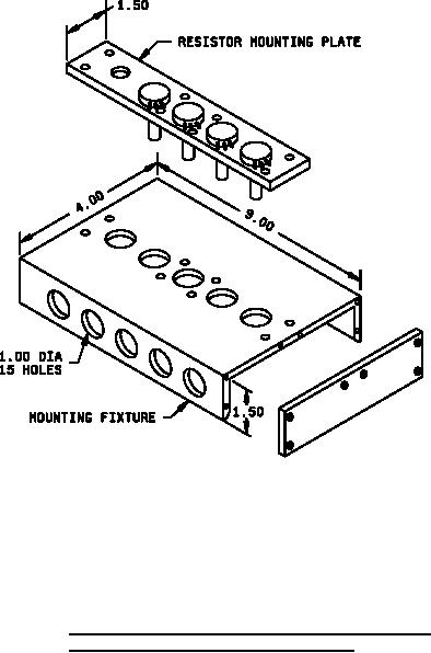
Inches
mm
Inches
mm
1.00
25.40
4.00
101.60
1.50
38.10
9.00
228.60
NOTES:
1. Dimensions are in inches. Metric equivalents are given for general information only
2. Tolerance is ±0.02 inch (0.51 mm).
FIGURE 6. Suggested mounting fixture and resistor mounting plate
for shock and high frequency vibration tests.
21
For Parts Inquires call Parts Hangar, Inc (727) 493-0744
© Copyright 2015 Integrated Publishing, Inc.
A Service Disabled Veteran Owned Small Business