MIL-PRF-22684F
APPENDIX B
APPENDIX B
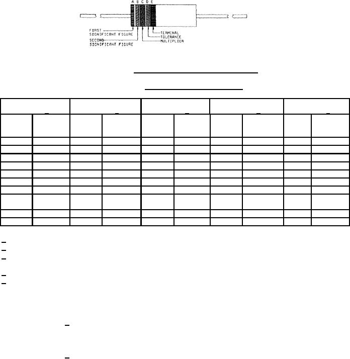
FIGURE B-1. Color-code marking for film-type resistors.
TABLE B-II. Color code for film-type resistors.
Band A 1/
Band B 2/
Band C 3/
Band D 4/
Band E 5/
Second
Resistance
First
significant
Tolerance
significant
Terminal
Color
figure
Color
Multiplier
Color
(Percent)
Color
Color
figure
±5
Black
0
Black
0
Black
1
Gold
White
Solderable
±2
Brown
1
Brown
1
Brown
10
Red
Red
2
Red
2
Red
100
Orange
3
Orange
3
Orange
1,000
Yellow
4
Yellow
4
Yellow
10,000
Green
5
Green
5
Green
100,000
Blue
6
Blue
6
Blue
1,000,000
Purple
7
Purple
7
Silver
0.01
(Violet)
(Violet)
Gold
0.1
Gray
8
Gray
8
White
9
White
9
1/ The first significant figure of the resistance value. (Bands A through D shall be of equal width).
2/ The second significant figure of the resistance value.
3/ The multiplier. (The multiplier is the factor by which the two significant figures are multiplied to yield the nominal
resistance value).
4/ The resistance tolerance.
5/ On film resistors, this band shall be approximately 1-1/2 times the width of other bands, and indicates a
solderable terminal.
Examples of color coding for film-type resistors:
5100 ohms +5 percent, solderable leads:
Band A, green; Band B, Brown; Band C, red; Band D, gold;
Band E, white (1-1/2 width of other bands).
5600 ohms +2 percent, solderable leads:
Band A, green; Band B, blue; Band C, red; Band D, red;
Band E, white (1-1/2 width of other bands).
25
For Parts Inquires call Parts Hangar, Inc (727) 493-0744
© Copyright 2015 Integrated Publishing, Inc.
A Service Disabled Veteran Owned Small Business